
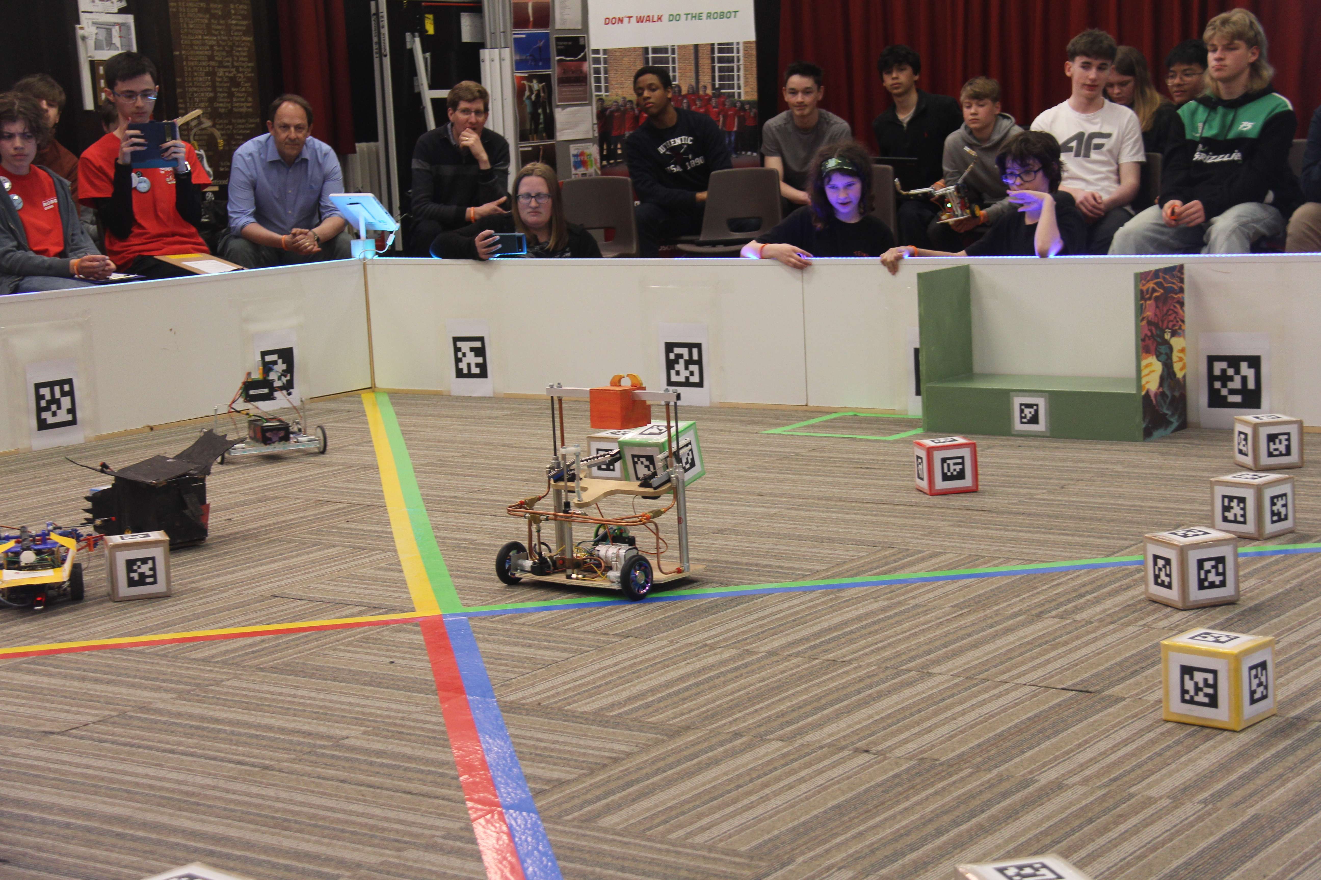
RoboCon 2026 Tributes to the Fallen
Good luck to all teams competing in the 2026 RoboCon competition! Read about the competition.
Read About It...RoboCon 2026 Calendar
View the key dates for RoboCon 2026.
| Event | Date | Notes |
|---|---|---|
| Competition | 8-9th April | Competition days, where teams compete in the arena to score points and win prizes! |
Our Sponsors
The RoboCon competition is only possible thanks to the generosity of our sponsors, we receive no other funding. Thank you for your support!
Latest News
RoboCon 2026 Patch 1 Released
Patch 1 released containing many bug fixes
Read More...Last updated: 29 November 2025
RoboCon 2026 Kick-Off
We have officially launched RoboCon 2026 with our exciting new competition: Tributes to the Fallen! In this years challenge only the most innovative tribute will rise victorious. May the games begin!
Read More...Last updated: 6 November 2025
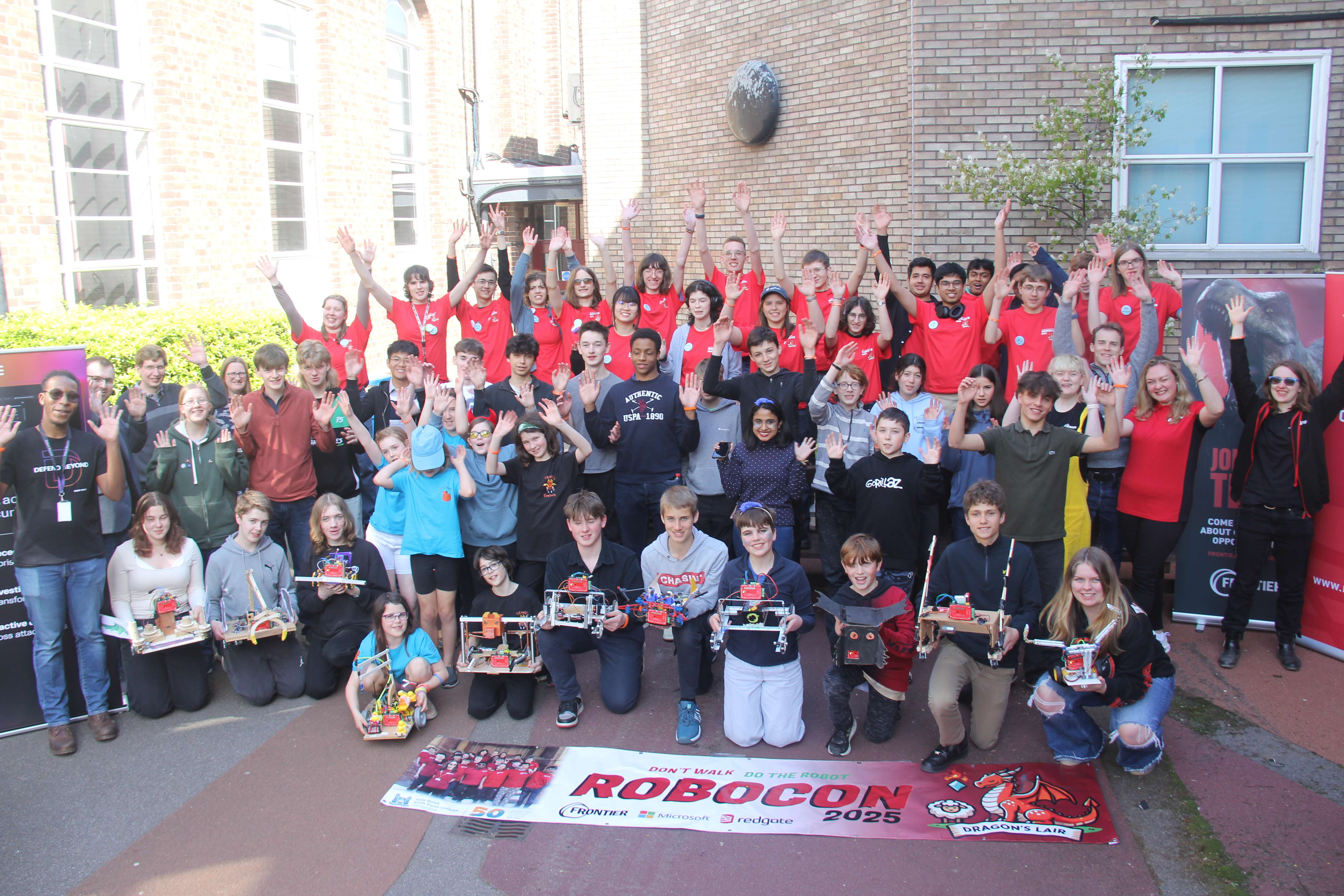
RoboCon 2025 Review
Read about this year's competition full of sheep, gems and epic robot dragons!
Read More...Last updated: 14 April 2025